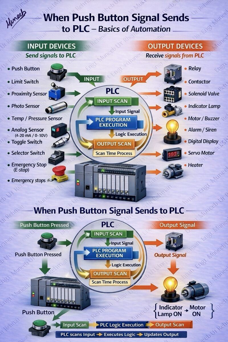
Understanding PLC Basics: From Input to Output Signal Flow 🔷
This image clearly explains the fundamental working principle of a PLC (Programmable Logic Controller) in an automation system.
👉 Step-by-Step Working:
1️⃣ Input Devices (Field Signals)
Devices like push buttons, limit switches, proximity sensors, and temperature/pressure sensors send signals to the PLC.
➡️ These are the inputs that tell the system what is happening in real-time.
2️⃣ Input Scan
The PLC continuously scans all input signals and updates their status in memory.
3️⃣ Program Execution (Logic Processing)
The PLC executes the control logic (Ladder Logic / Program) based on the input conditions.
➡️ This is where decision-making happens.
4️⃣ Output Scan
After processing, the PLC updates the output status.
5️⃣ Output Devices (Field Actions)
Devices like relays, contactors, motors, lamps, and alarms receive signals from the PLC and perform actions.
➡️ Example: Press push button → PLC processes → Motor starts & lamp turns ON.
🔁 This entire cycle is called the PLC Scan Cycle, and it repeats continuously within