

🔷 Fundamental Digital Logic Gates – The Building Blocks of Digital Circuits 🔷
Every modern electronic system—from simple controllers to advanced automation—relies on digital logic gates. This visual breaks down the core gates that form the foundation of digital electronics and PLC logic.
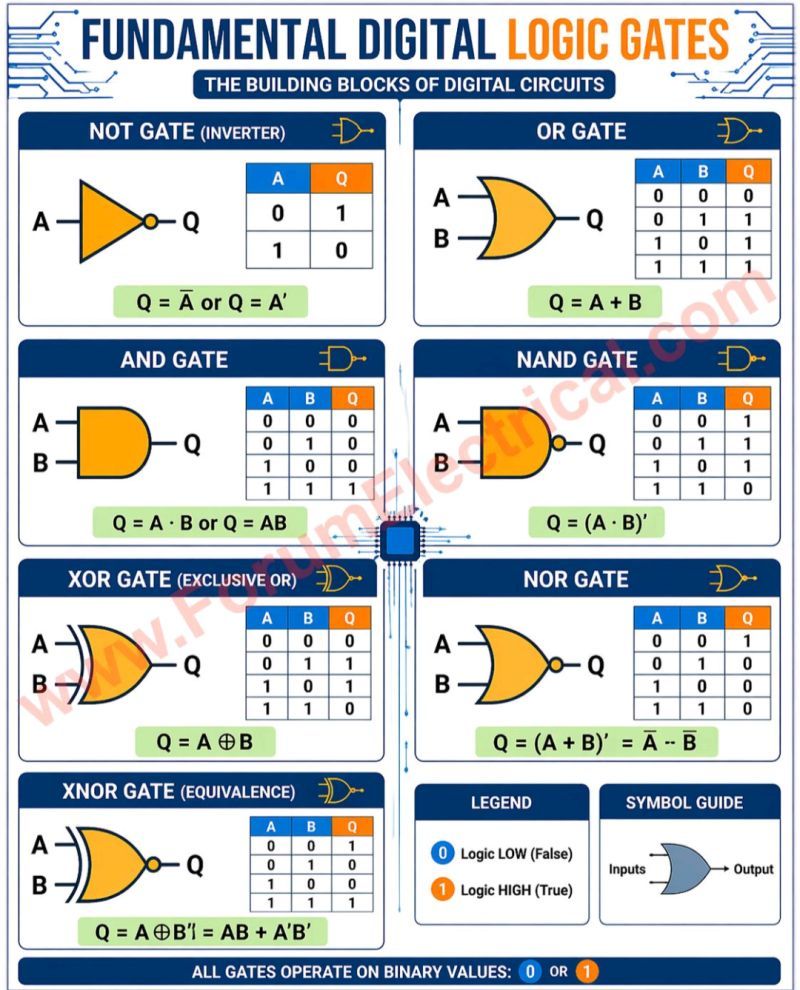
🔹 NOT Gate (Inverter)
Reverses the input signal. If input is 1, output becomes 0 and vice versa.
🔹 OR Gate
Output is HIGH when any one of the inputs is HIGH.
🔹 AND Gate
Output is HIGH only when all inputs are HIGH.
🔹 NAND Gate
Opposite of AND. Output is LOW only when all inputs are HIGH.
🔹 XOR Gate (Exclusive OR)
Output is HIGH when inputs are different.
🔹 NOR Gate
Opposite of OR. Output is HIGH only when all inputs are LOW.
🔹 XNOR Gate (Equivalence)
Output is HIGH when inputs are same.
📊 Each gate operates on binary values:
➡️ 0 = LOW (False)
➡️ 1 = HIGH (True)
💡 These simple logic functions are the backbone of:
✔️ PLC programming
✔️ Automation systems
✔️ Microcontrollers & processors
✔️ Digital electronics
Understanding these basics is essential for anyone working in Electrical & Instrumentation (E&I), automation.